
Carbon dioxide is one of those industrial gases that stays invisible until it stops arriving. A brewery without it cannot carbonate. A meat processor without it cannot chill. A welding shop without it cannot shield a bead. A greenhouse without it grows slower tomatoes. And yet for decades, most businesses simply bought CO2 in cylinders or bulk road tankers, paid whatever the market asked, and absorbed the shortages when merchant supply tightened.
That calculation has changed. Cylinder and bulk prices have climbed, supply has become unpredictable in several regions, and – critically – a large number of industrial processes throw away a CO2-rich stream every single day. Fermentation tanks vent it. Ammonia reformers produce it. Lime kilns, hydrogen units, ethanol distilleries, biogas upgraders and flue stacks all carry carbon dioxide that can be captured, cleaned and sold or self-consumed.
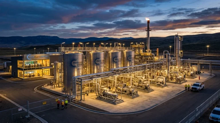
This is the reasoning behind the growth in demand for CO2 production plants ↗, CO2 generation plants ↗ and CO2 recovery plants ↗. Rather than buying a molecule, more plants are choosing to make it or recover it on site.
This guide walks through the whole subject – how a CO2 plant manufacturer approaches engineering and plant design, how capacity is selected, what recovery technology actually does, how purification and liquefaction work, how storage is sized, and what installation, commissioning and after-sales service should look like. It is written for plant heads, project engineers, procurement teams and business owners evaluating a carbon dioxide project for the first time.
Understanding the three plant types
People use the terms interchangeably, but they describe genuinely different machines. Getting the distinction right early saves a great deal of money later.
CO2 Generation Plants
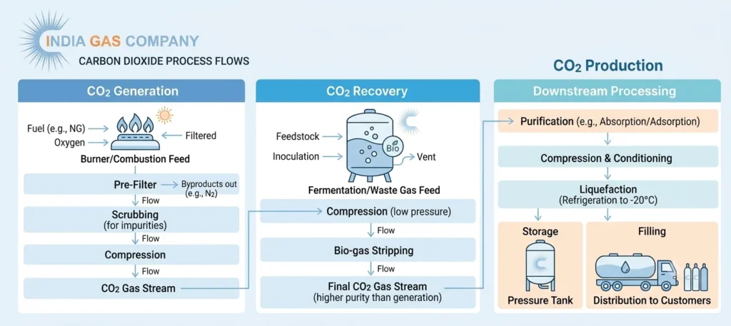
A CO2 generation plant creates carbon dioxide deliberately by burning a clean fuel – natural gas, LPG, kerosene or light diesel oil – in a controlled burner. The resulting flue gas, rich in CO2, is cooled, scrubbed and passed through a chemical absorption system (typically a MEA or activated amine solution) that selectively picks up the carbon dioxide and releases everything else. The rich solution is then heated in a stripper, which drives the CO2 back out in concentrated form, ready for drying and liquefaction.
Generation plants make sense where no CO2-bearing waste stream exists on site but reliable, independent supply is needed. Beverage bottlers in remote locations, standalone dry ice producers and fabrication units far from merchant depots often go this route.
CO2 Recovery Plants
A CO2 recovery plant does not create anything. It captures carbon dioxide that a process is already producing and would otherwise vent. The classic example is a brewery or distillery, where fermentation liberates roughly 0.45–0.50 kg of CO2 for every litre of alcohol produced. Ammonia plants, ethanol units, hydrogen reformers, biogas plants and lime kilns are equally strong candidates.
Because the feed gas is already concentrated – often 95–99% CO2 before treatment in a fermentation application – a recovery plant skips the combustion and absorption stages entirely. It is cheaper to run, consumes less energy per tonne, and turns a waste stream into either a cost saving or a revenue line. For most sites that have a suitable source, CO2 recovery plants offer the shortest payback of the three options.
CO2 Production Plants
CO2 production plant is the broader commercial term, usually applied to a facility built to produce liquid carbon dioxide for sale – filling cylinders, loading road tankers, or supplying dry ice. A production plant may be fed by generation, by recovery, or by natural CO2 wells, and it always includes the downstream package: purification, liquefaction, bulk storage and a filling station.
A capable CO2 plant manufacturer should be able to advise honestly on which of the three routes fits a given site, rather than selling whichever unit is easiest to build.
Engineering: the work that happens before any steel is cut
Engineering is where a carbon dioxide project is won or lost. It is also, unfortunately, where buyers are most tempted to economise.
The engineering phase begins with feed gas characterisation. Nobody can design a purification train without knowing what is in the gas. A fermentation stream carries ethanol, acetaldehyde, esters, sulphur compounds and water vapour.
A flue gas stream carries oxides of nitrogen, oxides of sulphur, oxygen, carbon monoxide and particulates. An ammonia plant stream carries hydrogen, methane and traces of oil.
Each of these demands a different arrangement of scrubbers, catalysts and adsorbents. Designing from a generic template – without sampling the actual gas – is how plants end up failing purity tests months after handover.
Good engineering for a CO2 plant includes:
- Feed gas analysis and mass balance across the full production range, not just the design point
- Process flow diagrams (PFDs) establishing every major unit operation and stream condition
- Piping and instrumentation diagrams (P&IDs) defining valves, interlocks, relief paths and control philosophy
- Heat and energy balance, which drives refrigeration sizing and ultimately operating cost per tonne
- Equipment datasheets for compressors, heat exchangers, adsorbers, columns and pumps
- Structural and civil load data for foundations, skid mounting and vessel supports
- Electrical load schedules and control system architecture (PLC/SCADA or DCS)
- Hazard identification (HAZOP), relief valve sizing and asphyxiation risk assessment
Carbon dioxide is heavier than air, colourless and odourless. It pools in pits, trenches and basements. Serious engineering treats leak detection, forced ventilation and confined-space design as non-negotiable rather than as optional extras.
Standards matter too. Beverage-grade CO2 is judged against ISBT (International Society of Beverage Technologists) quality guidelines and EIGA/CGA specifications.
Food-grade product must satisfy FSSAI requirements in India and equivalent food safety codes elsewhere.
Medical-grade CO2 sits under pharmacopoeial standards. The purity target chosen at engineering stage dictates the entire purification design – it cannot be retrofitted cheaply.
Across 23 years of engineering work, India Gas Company ↗ has found that the single most common cause of underperforming carbon dioxide plants is not poor equipment. It is engineering that skipped the feed gas study.
Plant Design: turning process into a workable layout
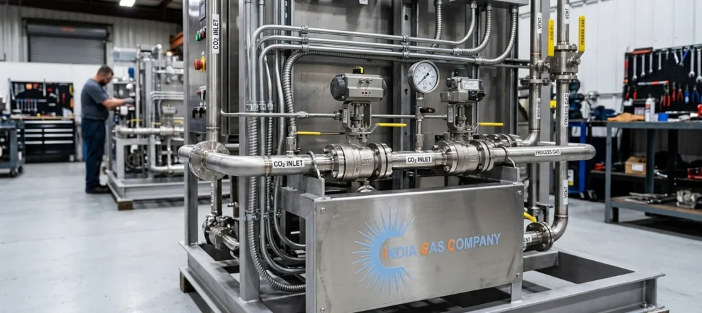
Plant design translates the engineering package into something that can actually be built, operated and maintained on a real piece of ground.
Skid-mounted versus field-erected. Smaller capacities – broadly up to 20–25 TPD – are usually best delivered as pre-assembled skids. Modules are built, wired, piped and pre-tested in the fabrication shop, then trucked to site. Site work reduces to placing skids, connecting utilities and interconnecting piping. Installation time falls sharply and quality control is far easier in a workshop than on a monsoon-soaked site. Larger plants move toward field erection, with critical modules still skid-built wherever possible.
Layout and spacing. Good plant design keeps the compressor house acoustically isolated, places the refrigeration package where condenser airflow is unobstructed, positions storage tanks with tanker access and safe relief venting, and leaves genuine maintenance access around every exchanger and adsorber. It is remarkably common to see plants where a shell-and-tube bundle cannot be pulled without dismantling adjacent piping. That is a design failure, and it costs the owner every year for the life of the plant.
Utilities integration. A CO2 plant needs cooling water, instrument air, electrical power and sometimes steam. Design should tie into existing utilities where capacity allows, rather than duplicating infrastructure.
Automation level. Modern plant design leans heavily on PLC control with HMI operation, automatic start-up and shutdown sequences, purity interlocks that divert off-spec gas before it reaches storage, and remote monitoring so that a manufacturer’s engineer can diagnose a fault without travelling. Automation reduces manpower requirement to a single operator per shift in most installations.
Expansion planning. Sensible plant design anticipates growth. Leaving space and tie-in points for a second compressor train or an additional storage tank costs almost nothing at design stage and saves enormous disruption three years later.
Capacity: Choosing the Right Size
Capacity for carbon dioxide plants is quoted in TPD – tonnes per day of liquid CO2. Commercial units commonly range from around 3 TPD at the small end to 250 TPD and beyond for large merchant production plants.
Sizing correctly requires balancing several inputs:
Available feed gas. In a recovery application, this is the hard ceiling. A distillery producing a given volume of alcohol liberates a calculable quantity of CO2. Recovery is never 100% – realistic designs capture 85–95% of what is available, with losses in start-up, purging and transitions. There is no point sizing a 30 TPD CO2 recovery plant for a stream that can sustain 18 TPD.
Consumption profile. Own-use plants should be sized against realistic peak demand, not annual average. A beverage plant’s summer peak can be double its winter trough.
Merchant sales potential. If surplus product will be sold, market study matters – how many cylinder fillers, welding shops, cold chain operators and food processors sit within economical transport radius?
Feed availability hours. A plant fed by a batch fermentation process does not receive gas continuously. Buffer gas holders smooth this out, but design must reflect it.
Turndown. A plant that can only run at 100% capacity is a liability. Well-designed plants hold specification down to 40–50% of rated capacity, so production can follow demand instead of running to stock.
Undersizing forces continued merchant purchases and undermines the business case. Oversizing wastes capital and hurts efficiency, since compressors and refrigeration run inefficiently far below design load. This is one of the judgements where a CO2 plant manufacturer with a large installed base adds real value – having built across many capacities and industries, the pattern recognition is simply better.
CO2 Recovery Technology
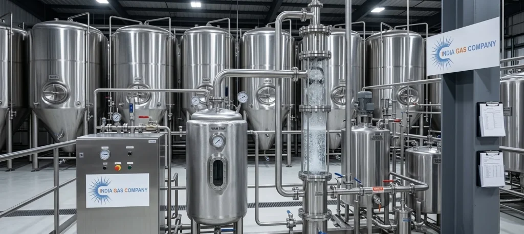
The heart of any CO2 recovery plant is the sequence that takes a dirty, wet, low-pressure gas and turns it into clean, dry, high-pressure product. The sequence varies by source, but the logic is consistent.
Collection and Buffering
Gas is collected from fermenters, reactor vents or stack tie-ins through a header and routed to a foam trap or gas balloon. The foam trap catches carryover liquid and froth from vigorous fermentation. A buffer holder – often a low-pressure gas balloon – evens out flow variations so the compressor sees a steady feed rather than surging with every tank.
Water scrubbing
The gas passes upward through a packed scrubbing column against a downward water flow. Water-soluble contaminants – ethanol vapour, aldehydes, organic acids and many flavour compounds – are washed out here. In fermentation applications this stage does a large share of the purification work.
Compression
A two-stage oil-free or oil-lubricated reciprocating compressor raises pressure to roughly 15–20 bar, with intercooling and after-cooling between and after stages. Condensate drops out at each cooling step. Where oil-lubricated machines are used, oil removal filtration follows immediately.
Dedicated recovery variants
- Flue gas and post-combustion recovery uses amine absorption – MEA, MDEA or proprietary blends – to separate CO2 from nitrogen-rich exhaust, followed by steam stripping to release it. This is essential where CO2 concentration in the feed is low (typically 8–15%).
- PSA (Pressure Swing Adsorption) is applied where CO2 must be separated from hydrogen or methane, as in reformer offgas or biogas upgrading.
- Membrane separation is used for pre-concentration in some biogas and landfill gas applications, often ahead of a polishing stage.
- Fermentation recovery needs no separation stage at all, since the gas is already highly concentrated – only cleaning.
The technology selection follows entirely from feed composition. A serious CO2 plant manufacturer will sample and analyse before recommending a route.
CO2 purification: getting to beverage and food grade
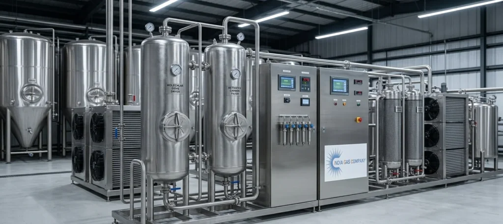
Purification is where a plant earns its purity certificate. For beverage-grade product, total impurities must sit in the parts-per-million range, and specific compounds – sulphur species, aldehydes, aromatic hydrocarbons, benzene – are held to parts-per-billion limits. Taste and odour testing is part of the acceptance criteria, because a carbonated drink is an extraordinarily sensitive detector of trace contamination.
A typical CO2 purification train includes:
Oil removal filtration. Coalescing filters and carbon filters strip lubricant carryover from compression. Any oil reaching downstream adsorbents ruins them.
Dehydration. Twin-tower adsorbent dryers – activated alumina, molecular sieve, or a layered combination – remove moisture to a dew point below –60 °C. Towers alternate between adsorption and regeneration, with regeneration heat supplied electrically or by hot gas. This stage is not optional: residual water forms ice and dry ice in the liquefaction section and corrodes downstream equipment in the presence of CO2.
Activated carbon purification. A dedicated carbon bed adsorbs hydrocarbons, sulphur compounds, aldehydes and odour-bearing trace organics. This is the stage that determines whether the product tastes clean.
Catalytic oxidation. Where carbon monoxide, hydrogen or residual hydrocarbons are present – common in flue gas and reformer sources – a catalytic converter oxidises them at elevated temperature before final polishing.
Stripping/distillation column. In high-specification plants a stripper column removes the last non-condensable gases (oxygen, nitrogen, argon) that would otherwise depress product quality and raise pressure in storage.
Online analysers. Continuous measurement of moisture, oxygen and total hydrocarbons, with automatic diversion of off-spec product, is what makes consistent quality repeatable rather than lucky.
Well-executed CO2 purification reliably delivers 99.9% to 99.998% purity depending on configuration and feed.
Liquefaction
Carbon dioxide is stored and transported as a liquid because liquid is dense. One tonne of CO2 gas at atmospheric pressure occupies roughly 500 cubic metres. As liquid, it fits in under a cubic metre.
CO2 liquefaction takes place in a shell-and-tube or plate condenser where clean, dry, compressed gas is cooled against a refrigerant. Typical operating conditions sit around 15–20 bar and –25 °C to –35 °C – comfortably inside the liquid region of the carbon dioxide phase diagram and safely above the triple point at 5.18 bar and –56.6 °C, below which solid dry ice forms and blocks equipment.
Refrigeration is supplied by a closed-loop system using ammonia (R717), R404A, R507 or increasingly low-GWP alternatives, driven by screw or reciprocating compressors with air-cooled or evaporative condensers. Ammonia offers excellent thermodynamic efficiency but demands stricter safety engineering; synthetic refrigerants are simpler to handle but carry environmental and regulatory considerations.
Energy consumption in liquefaction dominates the operating cost of a CO2 plant. Design choices that seem minor at purchase – condenser approach temperature, exchanger surface area, compressor selection, heat recovery from intercoolers – translate directly into rupees per tonne for the next fifteen years. This is precisely where a low capital quote can quietly become the expensive option.
Storage
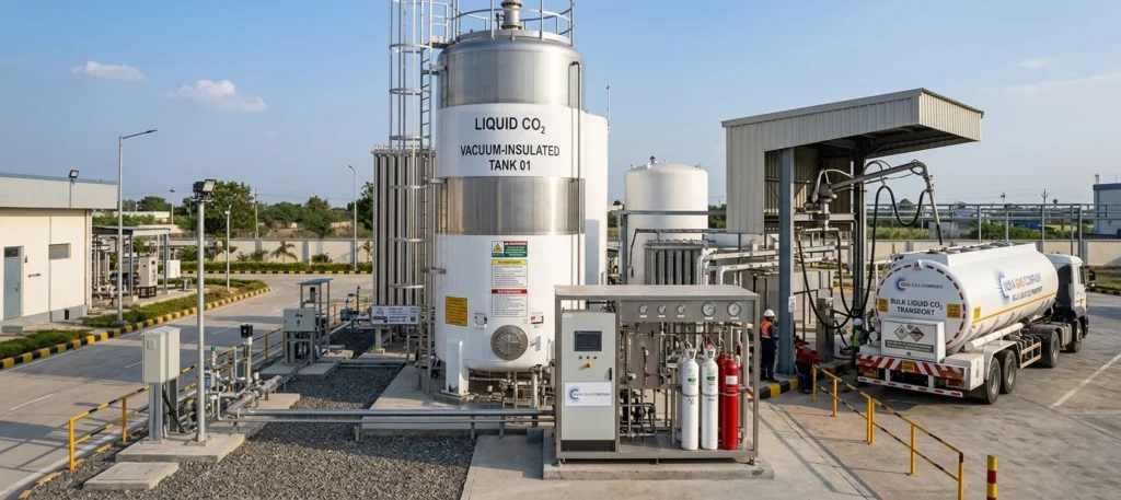
Liquid CO2 is held in vacuum-insulated or polyurethane-insulated pressure vessels, typically maintained at 15–20 bar and around –20 °C to –30 °C. Vessels are supplied in horizontal or vertical configuration from roughly 5 tonnes up to 100 tonnes and above, designed and certified to ASME Section VIII Div 1, PED or IS standards, with statutory approval as applicable.
Key elements of a well-designed storage system:
- Refrigeration maintenance unit – a small dedicated chiller that removes heat ingress and holds tank pressure steady without venting. Without it, product is lost continuously through relief valves.
- Dual safety relief valves with a changeover arrangement, allowing one to be tested or replaced while the vessel stays protected.
- Level, pressure and temperature instrumentation with high/low alarms and remote indication.
- Vaporisers – ambient or electric – for users drawing gaseous CO2.
- Filling station for cylinder filling, tanker loading or dry ice production.
Storage capacity is generally sized for two to four days of production or consumption, with adjustment for tanker logistics and seasonal demand. Undersized storage forces the plant to modulate constantly; oversized storage ties up capital in an expensive vessel.
Installation
Installation converts equipment into an operating asset. It typically runs four to twelve weeks depending on capacity and how much of the plant arrived as pre-tested skids.
A structured installation covers:
- Site readiness – civil foundations, plinths, drainage, ventilation, statutory clearances
- Equipment placement – crane planning, skid setting, vessel erection and alignment
- Piping and interconnection – fabrication, welding, supports and expansion provision
- Electrical and instrumentation – cabling, panels, field instruments, earthing and loop checks
- Utility connections – cooling water, instrument air, power, steam where applicable
- Pressure testing and leak detection – hydro and pneumatic testing of all pressure circuits
- Purging and drying – displacing air and moisture before introducing product gas
- Safety systems – CO2 leak detectors, ventilation interlocks, emergency shutdown, signage
The most frequent cause of installation overruns is not the equipment. It is civil work that was not ready, or utilities that were not available at the promised capacity. A manufacturer who issues clear civil and utility drawings early, then follows up on site readiness, prevents most of these delays.
Commissioning
Commissioning is the disciplined handover from construction to production, and it deserves more time than most project schedules allow.
Pre-commissioning covers instrument calibration, motor rotation checks, interlock verification, relief valve settings and dry runs of the control sequence.
Cold commissioning runs the plant on air or nitrogen to confirm mechanical integrity and control logic without product.
Hot commissioning introduces feed gas, brings up compression and refrigeration, establishes liquefaction, and stabilises the process at design conditions.
Performance guarantee testing demonstrates the contracted capacity, purity and specific energy consumption over a sustained continuous run – commonly 48 to 72 hours. Product samples go to an accredited laboratory for full analysis against ISBT, FSSAI or the relevant specification.
Operator training runs alongside, covering normal operation, start-up and shutdown, adsorbent regeneration cycles, alarm response, routine maintenance and – importantly – emergency procedures for CO2 release.
Commissioning ends with documentation: as-built drawings, O&M manuals, calibration certificates, test reports, spare parts list and warranty terms. A plant handed over without a complete document set will cost its owner in every future audit, modification and inspection.
After-sales service
A carbon dioxide plant is a fifteen-to-twenty-five-year asset. The purchase decision is really a decision about who will support it for that period.
Meaningful after-sales service includes:
- Annual maintenance contracts with scheduled preventive visits
- Spare parts availability – valves, seals, gaskets, filter elements, compressor components – held in domestic stock rather than imported on demand
- Adsorbent and catalyst replacement on a planned cycle, typically three to five years for molecular sieve and activated carbon
- Remote monitoring and diagnostics via the plant PLC, so many faults can be identified before an engineer travels
- Response time commitments for breakdowns, with defined escalation
- Refresher operator training, particularly after staff turnover
- Retrofits and upgrades – capacity expansion, automation improvement, energy efficiency modification, refrigerant transition
Unplanned downtime on a CO2 plant does not cost only lost production. It forces emergency merchant purchases at spot prices, and in a beverage or food operation it can halt packaging lines entirely. The economics of good service are not subtle.
This is one reason buyers increasingly weight proximity and track record heavily. India Gas Company, with 23 years in the field and more than 100 completed projects, maintains service engineering and spares within reach of the plants it has supplied – which matters far more on a Sunday night than it does in a tender comparison.
Industries served
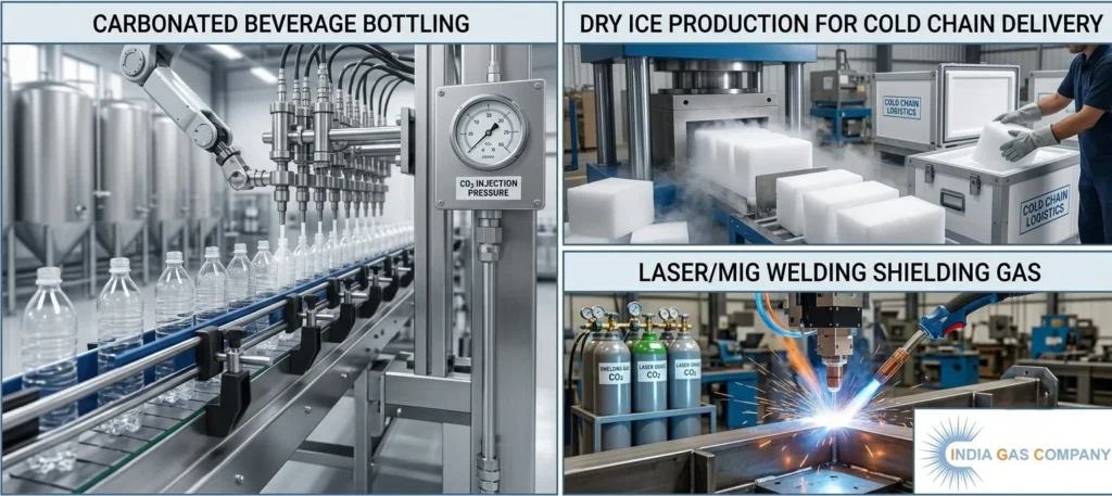
Food and beverage. Carbonation of soft drinks, beer and sparkling water; modified atmosphere packaging; cryogenic freezing and chilling; carbonated beverage plants are the single largest consumer of beverage-grade CO2.
Breweries and distilleries. Both a source and a consumer – fermentation CO2 is recovered, purified and returned for purging, counter-pressure filling and carbonation. Among the most compelling cases for a CO2 recovery plant.
Welding and fabrication. MIG/MAG shielding gas, supplied pure or blended with argon.
Pharmaceutical and healthcare. Medical-grade CO2 for insufflation and laboratory use; supercritical CO2 for extraction and sterilisation.
Oil and gas. Enhanced oil recovery, well stimulation, pipeline purging and inerting.
Chemical and fertiliser. Urea synthesis, methanol production, pH control and feedstock use – ammonia plants are a classic recovery source.
Agriculture and horticulture. Greenhouse CO2 enrichment measurably increases yield in protected cultivation.
Cold chain and logistics. Dry ice for pharmaceutical and food transport, and for temperature-controlled last-mile delivery.
Water treatment. CO2 for pH adjustment, replacing mineral acids more safely.
Electronics and metal. Inerting, cleaning, and supercritical CO2 processes.
Ethanol and biofuel. Fermentation-based ethanol plants generate large, clean CO2 streams – often the most economically attractive recovery projects of all.
Choosing a CO2 plant manufacturer
Capital cost is the easiest number to compare and the least informative. Over a plant’s working life, energy and maintenance typically outweigh the purchase price several times over. The questions worth asking are different:
- Has the manufacturer-built plants of this capacity, on this feed gas, for this industry before? Reference sites are worth visiting.
- Does the offer include a genuine feed gas study, or a template design?
- What is the specific energy consumption guarantee in kWh per tonne, and is it contractual?
- Is a purity guarantee offered against a named standard – ISBT, FSSAI, EIGA – with third-party lab verification?
- What is the turndown range, and does specification hold at minimum load?
- Where are spares stocked, and what is the committed response time?
- Who performs installation and commissioning – the manufacturer’s own engineers, or subcontractors?
- What documentation and statutory approvals are included?
India Gas Company (+91 8971091010) has worked across this space for 23 years, with more than 100 completed projects spanning CO2 production plants, CO2 generation plants and CO2 recovery plants across food and beverage, distillery, chemical, fertiliser, pharmaceutical and industrial gas applications. That history is useful mainly because it removes guesswork – capacity selection, purification configuration and layout decisions come from what has actually worked on comparable sites, not from a catalogue.
Whether the right answer for a particular site is a compact 5 TPD recovery unit tied to a fermentation header, or a 100 TPD merchant production facility with a full filling station, the honest starting point is the same: analyse the gas, quantify the demand, and size from evidence.
Frequently Asked Questions (FAQs)
Q1. What purity can a CO2 recovery plant achieve?
With a complete purification train, 99.9% to 99.998% is routinely achievable – sufficient for beverage and food grade against ISBT and FSSAI criteria.
Q2. How long does a project take end to end?
Typically six to twelve months from order to commissioning, depending on capacity, degree of skid-mounting and site readiness. Civil work and statutory approvals usually sit on the critical path.
Q3. What is the payback period?
For recovery plants with a strong existing feed stream, two to four years is common, driven by avoided merchant purchase. Generation plants take longer since fuel is an ongoing cost.
Q4. What utilities are required?
Electrical power, cooling water, instrument air, and in some configurations steam for adsorbent or amine regeneration. Load schedules are issued during engineering.
Q5. How much manpower does the plant need?
Automated plants generally require one trained operator per shift, with a shared maintenance resource.
Q6. Can an existing plant be expanded?
Yes, if the original layout allowed for it. Adding a compressor train, refrigeration capacity or storage is far simpler when tie-in points were provided at design stage.
Discuss Your CO2 Project
Every site is different – different feed gas, different demand curve, different constraints. The most useful next step is a short technical conversation, followed by feed gas analysis and a capacity study.
India Gas Company offers a no-obligation feasibility assessment covering:
• Feed gas sampling and analysis
• Recommended plant type – production, generation or recovery
• Capacity and configuration proposal
• Budgetary capital estimate and operating cost projection
• Indicative payback calculation and project timeline
Share your feed gas source, required capacity in TPD and target purity grade, and our engineering team will revert with a preliminary proposal.
Enquire Now: Tell us about your CO2 requirement and we will help you size it correctly the first time.