
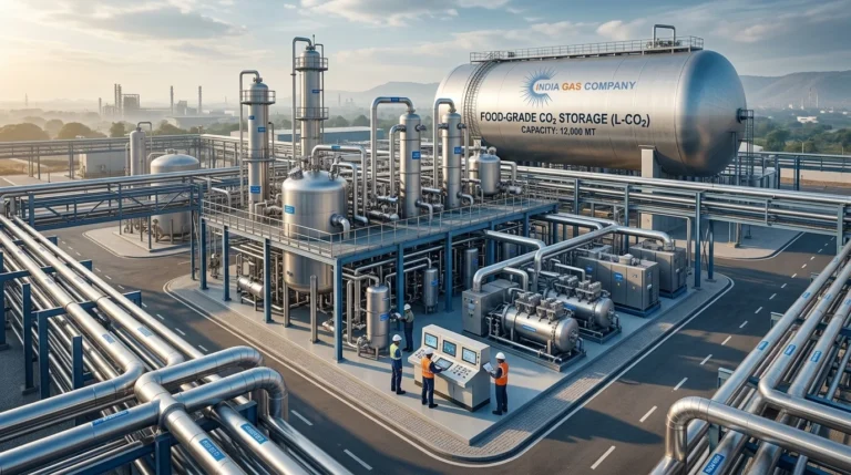

Carbon dioxide (CO₂) is an essential industrial gas used across beverage carbonation, food processing, dry ice manufacturing, welding, water treatment, chemical processing, pharmaceuticals, and several other industries. With increasing demand for reliable and high-purity CO₂, companies are increasingly investing in captive CO₂ generation and recovery systems.
A properly engineered CO2 Recovery Plant Setup allows industries such as ethanol distilleries and breweries to recover CO₂ generated as a by-product and convert it into commercially valuable liquid CO₂. At the same time, a well-designed CO2 Production Plant Setup can provide a dependable source of purified and liquefied CO₂ for industrial or food-grade applications.
The choice of technology, plant capacity, raw gas characteristics, purification requirements, utilities, storage capacity, and end-use specifications all influence the final plant design.
This article explains the major considerations involved in a CO2 Recovery Plant Setup and CO2 Production Plant Setup, along with technical specifications based on a 40 MTPD food-grade CO₂ plant specification.
What is a CO2 Recovery Plant Setup?
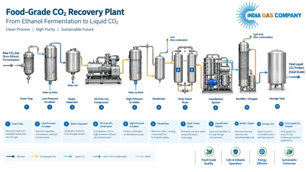
A CO2 Recovery Plant Setup is an integrated system designed to capture CO₂-rich gas from an industrial process, purify it, compress it, dry it, liquefy it, and store the resulting liquid CO₂.
One of the most common applications is CO₂ recovery from fermentation processes. During grain-based ethanol production, fermentation generates a CO₂-rich gas stream. Instead of releasing this gas into the atmosphere, a recovery plant can process it into high-purity liquid CO₂.
The referenced plant specification is based on a grain-based ethanol distillery and is designed for a liquid CO₂ production capacity of 1,700 kg/hr, equivalent to approximately 40 MTPD. The specified food-grade product purity is 99.99% v/v, with an oxygen specification of less than 10 ppm maximum.
A complete CO2 Recovery Plant Setup therefore involves considerably more than simply collecting fermentation gas. It requires multiple purification and conditioning stages to achieve the required product quality.
CO2 Production Plant Setup: From Raw CO2 Gas to Liquid CO2
A modern CO2 Production Plant Setup generally consists of several interconnected process stages.
The basic process sequence can be represented as:
Raw CO2 Gas → Foam Trap → Booster Blower → LP Scrubber → Moisture Separator → CO2 Compressor → HP Scrubber → Deodorizer → Dryer → Liquefaction → Rectification/Stripping → Liquid CO2 Storage
Each stage has a specific function and contributes to final CO2 quality.
For the referenced 40 MTPD system, the raw CO2 gas is specified at approximately 95–97% v/v minimum purity on a dry basis, with a temperature of 35–40°C and an inlet pressure requirement of approximately 200–300 mm WC.
CO2 Foam Trap
The first stage in a fermentation-based CO2 Recovery Plant Setup is generally protection against foam carryover.
Fermentation gases can occasionally carry foam from fermenters into the gas recovery system. A foam trap acts as an accumulator and prevents this material from entering downstream equipment.
The referenced design specifies an SS 304 CO₂ foam trap equipped with a water spray arrangement, pressure gauge, water-level gauge, sight/cleanout arrangement, and drain system.
Installing this equipment at an appropriate elevation between the fermenters and the recovery system helps protect downstream equipment.
CO2 Recovery Plant Setup With High-Efficiency Gas Scrubbing
Gas purification is one of the most important aspects of a CO2 Recovery Plant Setup.
Fermentation CO₂ may contain water-soluble contaminants, alcohols, acetaldehyde, moisture, and other impurities. These contaminants need to be removed before the gas reaches the compression, drying, and liquefaction stages.
Low-Pressure CO2 Scrubber
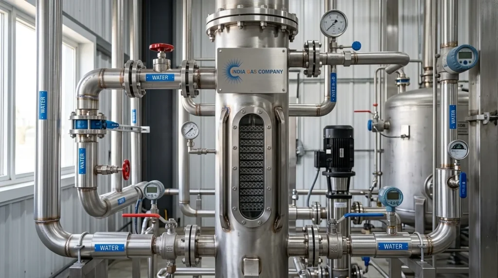
The referenced system uses an SS 304 low-pressure CO2 gas scrubber with structured packing.
The structured packing provides high-efficiency contact between the gas and scrubbing water. According to the supplied specification, the scrubber is designed for 99.9%+ removal of ethanol or alcohol, while also helping remove acetaldehyde and entrained water droplets.
The design uses once-through scrubbing rather than a conventional recirculation arrangement, which can help reduce water, power, and effluent requirements.
A CIP system with an SS tank and circulation pump is also included for cleaning the structured packing and scrubber.
CO2 Compressor in a CO2 Production Plant Setup
After initial gas purification, the CO₂ is compressed.
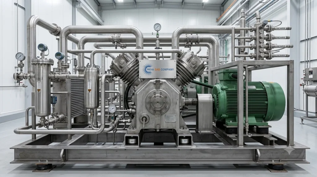
The referenced plant includes a 1,700 kg/hr, two-stage, non-lubricated CO₂ gas compressor. The compressor is specifically intended for CO₂ applications where petroleum lubricant contamination cannot be tolerated.
The specified compressor package includes:
- Two-stage compression
- Oil-free/non-lubricated operation
- TEFC motor
- Intercooler and aftercooler
- Stainless-steel cooler tubes
- Moisture separators and traps
- Teflon piston rings
- Stainless-steel cushioned valves
- Automatic capacity control through unloaders
These features are particularly important in a food-grade CO2 Production Plant Setup, where product contamination must be controlled.
High-Pressure Scrubbing and CO2 Purification
Following compression, the gas undergoes additional purification in a high-pressure scrubber.
The supplied specification includes an SS 304 high-pressure CO2 scrubber with a high-pressure water pump. Like the low-pressure scrubber, it uses structured packing and is designed to remove water-soluble contaminants.
The system is specified to remove 99.9%+ of ethanol or alcohol and also assists in removing acetaldehyde. A high-efficiency demister pad prevents entrained water from reaching downstream equipment.
For a reliable CO2 Recovery Plant Setup, this purification stage is important because contamination entering subsequent equipment can increase maintenance requirements and adversely affect final CO2 quality.
Deodorizer and Dryer in a CO2 Recovery Plant Setup
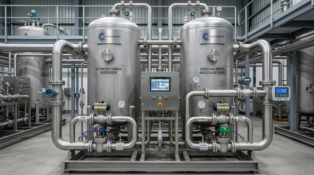
Once the major soluble contaminants have been removed, the gas must be deodorized and dried.
The supplied design incorporates a dual-tower CO2 gas deodorizer and a separate dual-tower CO2 gas dryer.
The deodorizer is designed to remove odor-causing impurities. The towers operate alternately: one tower remains online while the other is regenerated. Steam is used for regeneration.
The dryer removes residual moisture from the CO₂ stream. The specified maximum outlet dew point is −60°C at atmospheric pressure or 1 bar(a), with an online dew-point analyzer and manual override.
This drying stage is critical because moisture can create operational problems during refrigeration and liquid CO₂ production.
CO2 Production Plant Setup: Liquefaction System
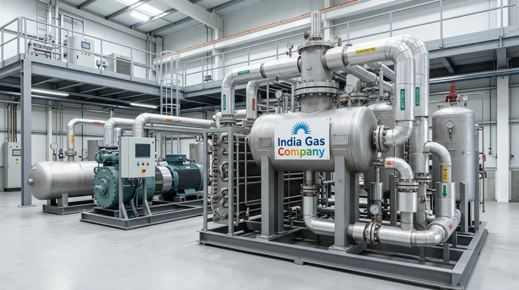
The heart of a liquid CO2 Production Plant Setup is the CO₂ liquefaction system.
Once the CO₂ has been purified and dried, it is compressed and cooled until it changes from gas to liquid.
In the referenced design, the CO₂ liquefaction system is designed to liquefy CO₂ vapor at approximately 17.5 bar(a) by cooling the vapor to approximately −26°C. The system is designed for continuous operation at 1,700 kg/hr.
The liquefaction package includes equipment such as:
- High-pressure CO₂ precooler
- Reciprocating compressor
- Refrigerant condenser/receiver
- CO₂ condenser
- Refrigeration system
- Associated controls and separators
The refrigeration system specified in the offer is an ammonia-based CO2 refrigeration system with a capacity corresponding to the 1,700 kg/hr plant.
CO2 Rectifier / Stripper
Liquefaction alone does not necessarily provide the final product quality required for food-grade applications.
The liquid CO₂ therefore passes through a rectification or stripping stage.
The referenced plant includes a liquid CO2 rectifier/stripper with reboiler and liquid CO2 transfer pump, with a specified capacity of 5,000 kg/hr. The liquid CO2 purity at the stripper outlet is specified as 99.99% v/v, with oxygen content below 10 ppm.
The stripper improves liquid CO2 quality by reducing non-condensable gases, including oxygen. Liquid CO2 is heated in the reboiler, and vapor CO2 rises through the packed bed, stripping non-condensable gases from the liquid feed.
This stage can be an important part of a food-grade CO2 Recovery Plant Setup.
CO2 Recovery Plant Setup: Liquid CO2 Storage
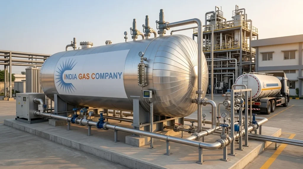
After purification and liquefaction, the product is transferred to bulk storage.
The referenced project includes one horizontal 100 KL liquid CO2 storage tank. The tank is specified with insulation and aluminum cladding, along with safety valves, process valves, and level measurement.
The technical specification states:
- Storage capacity: 100 KL
- Shell material: SA 516 Gr. 70
- Dish end: SA 516 Gr. 70
- Nozzle pipes: SA 333 Gr. 6
- Nozzle flanges: SA 350 LF2
- Pressure-part fasteners: SA 320 Gr. L7 / SA 194 Gr. 7
- Gasket: Teflon / CAF
- Insulation: 200 mm
- Cladding: 20 SWG aluminium
The design pressure specified for the equipment is 24 bar plus static pressure, while operating pressure is 19.5 bar. The specified operating temperature is below −26°C, with a hydro-test pressure of 35 kg/cm²g.
Utilities Required for CO2 Production Plant Setup
Utility planning is a critical part of any CO2 Production Plant Setup.
The plant specification provides the following utility requirements for the 1,700 kg/hr system:
| Utility | Technical Requirement |
| Electrical supply | 440–480 V, 3-phase, 60 Hz, 4-wire |
| Power consumption stated | 395 kWh |
| Control supply | 220–240 V, 1-phase, 60 Hz |
| Motors | TEFC |
| Steam | 150°C, 3.0–3.5 kg/cm²g |
| Steam consumption | 200 kg/hr |
| Cooling water temperature | 32°C |
| Cooling-water pressure | 2.5–3.0 kg/cm²g |
| Cooling-water flow | 276 m³/hr |
| Process water | 1.05 m³/hr |
| Raw CO₂ purity | 95–97% v/v minimum, dry basis |
| Raw CO₂ temperature | 35–40°C |
| Raw CO₂ pressure | 200–300 mm WC |
| Product capacity | 1,700 kg/hr |
These values are taken from the design basis in the supplied technical offer.
Actual utility requirements for a new project should always be finalized against the selected equipment, site conditions, ambient conditions, raw-gas composition, operating philosophy, and applicable engineering standards.
PLC and Automation in a Modern CO2 Recovery Plant Setup
Automation plays a major role in maintaining consistent product quality and reliable plant operation.
The referenced CO2 Recovery Plant Setup includes a centralized PLC-based control panel and motor control center. The system includes an HMI and operating indications for run, stop, and trip conditions.
Instrumentation specified in the project includes:
- CO₂ gas flow meter
- Online dew-point analyzer
- CO₂ purity tester
- Pressure gauges
- Temperature gauges
- RTDs
- Pressure switches
- Level transmitters
- Safety valves
- Process valves
The CO₂ vapor flow meter specified is SS 316, with a digital display in kg/hr and a 4–20 mA output.
Automation can help operators monitor critical process parameters and maintain stable operation across purification, refrigeration, liquefaction, and storage.
Engineering and Safety Considerations for CO2 Production Plant Setup
A successful CO2 Production Plant Setup requires careful attention to pressure equipment design, piping, material selection, instrumentation, inspection, and commissioning.
The supplied tank specification references IS 2825, Class 1, 1969 with AMD-1, 1977, and SMPV(U) 1981, with flanges specified according to ANSI B16.5. The document also specifies inspection and testing requirements including radiography and stress relieving where applicable.
Interconnecting piping in the referenced design uses stainless steel for wet CO₂ up to the dryer inlet, while seamless carbon steel is specified for dry CO₂/liquid CO₂, refrigerant, cooling-water, and make-up-water services, subject to the detailed project design.
A detailed project should additionally address applicable local statutory approvals, pressure-vessel regulations, fire and safety requirements, electrical standards, hazardous-area requirements where applicable, and site-specific engineering conditions.
Why Choose a Turnkey CO2 Recovery Plant Setup?
For industries looking to establish their own CO₂ production capability, a turnkey approach can simplify project execution.
A complete CO2 Recovery Plant Setup can include:
- Process design and engineering
- Equipment manufacturing
- CO₂ purification system
- Gas compression system
- Deodorization and drying
- CO₂ liquefaction system
- Rectification/stripping
- Liquid CO₂ storage
- Piping and valves
- Electrical systems
- PLC/MCC automation
- Instrumentation
- Erection supervision
- Commissioning
- Performance testing
The referenced offer includes design, fabrication, supply, erection/commissioning supervision, interconnecting piping, electrical wiring, auxiliary testing equipment, and initial process media within the stated scope.
CO2 Recovery Plant Setup for Different Industries
Although fermentation-based recovery is a major application, CO₂ plants can be designed around different feed-gas sources.
Potential applications include:
- Ethanol distilleries
- Breweries
- Sugar industries
- Fertilizer plants
- Chemical plants
- Hydrogen and syngas processes
- Industrial gas applications
- Other CO₂-rich process streams
The supplied reference itself includes examples of CO₂ plants associated with distilleries, breweries, chemical processes, fertilizer-based sources, and other industrial applications.
Therefore, the appropriate CO2 Production Plant Setup should be selected based on the raw-gas source and composition rather than using a one-size-fits-all configuration.
CO2 Production Plant Setup: Key Factors to Consider Before Installation
Before starting a CO2 Production Plant Setup, the project owner should establish several critical parameters.
1. CO2 Source
Determine whether the raw gas comes from fermentation, chemical processing, fertilizer production, combustion, or another process.
2. Required Capacity
Plant capacity may be specified in kg/hr, MTPD, or another production basis. The referenced project is designed for 1,700 kg/hr, approximately 40 MTPD.
3. Raw Gas Composition
CO₂ concentration and impurities directly influence purification equipment and operating costs.
4. Product Specification
Food-grade CO₂ requires stringent control over contaminants, moisture, oxygen, odor, and other parameters.
5. Storage Requirement
Storage capacity should be selected according to production rate, customer demand, dispatch frequency, tanker availability, and operating philosophy.
6. Utilities
Electric power, cooling water, steam, process water, refrigeration, compressed air, and other utilities should be confirmed during engineering.
7. Site Conditions
Elevation, ambient temperature, available space, foundation conditions, equipment layout, and access for transportation and maintenance all affect plant design.
Conclusion: Building a Reliable CO2 Recovery Plant Setup
A successful CO2 Recovery Plant Setup is an integrated process rather than a single piece of equipment. Raw CO₂ must be collected, purified, compressed, dried, liquefied, rectified, and stored under controlled conditions.
Similarly, a reliable CO2 Production Plant Setup requires proper integration of process equipment, refrigeration, utilities, instrumentation, automation, storage, and safety systems.
The 40 MTPD reference design demonstrates how a complete food-grade CO₂ facility can be configured around a 1,700 kg/hr production capacity, with 99.99% v/v liquid CO₂ purity, oxygen below 10 ppm, dual-stage purification, drying to a specified −60°C dew point, CO₂ liquefaction at approximately 17.5 bar(a) and −26°C, rectification/stripping, and 100 KL bulk storage.
For a new project, however, the final CO2 Recovery Plant Setup should always be engineered around the customer’s actual raw-gas conditions, required product specification, production capacity, utility availability, storage requirements, site conditions, and applicable statutory standards.
A professionally engineered CO2 Production Plant Setup can transform a CO₂-rich waste or by-product stream into a valuable commercial product while improving resource utilization and creating an additional revenue opportunity for the plant owner.
You May Like:
🔗 Liquid CO₂: The Invisible Powerhouse Reshaping Modern India
🔗 Why CO2 Plant Setup Is a Must for All Distilleries and Ethanol Plants?


1 thought on “CO₂ Recovery Plant Setup and CO₂ Production Plant Setup: Complete Guide to Designing a Food-Grade CO₂ Plant”