
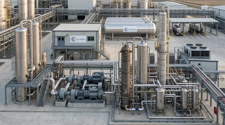

Carbon dioxide is no longer just a fermentation by-product to be vented into the atmosphere, it is a valuable industrial gas used across beverage bottling, food processing, dry ice manufacturing, welding, water treatment, and more.
For distilleries, breweries, and chemical plants that generate CO2 as a by-product, a well-engineered CO2 Recovery Plant Setup turns a waste stream into a revenue-generating, food-grade product.
This article walks through what a CO2 Recovery Plant Setup involves, the core equipment used, the technical parameters that define plant performance, and the design considerations that separate a reliable system from an inefficient one.
What Is a CO2 Recovery Plant Setup?
A CO2 Recovery Plant Setup is an integrated system that captures raw carbon dioxide gas, typically from fermentation in grain-based ethanol distilleries, sugar-based distilleries, or breweries and purifies it into liquid CO2 of food or industrial grade. The process removes moisture, odor-causing impurities, and non-condensable gases while compressing and liquefying the purified gas for storage.
A properly engineered CO2 Recovery Plant Setup typically delivers CO2 purity of 99.99% v/v, meeting ISBT (International Society of Beverage Technologists) standards accepted by global beverage companies. This level of purity is essential if the recovered CO2 is intended for carbonation in soft drinks or packaged beverages.
Why Invest in a CO2 Recovery Plant Setup?
Fermentation-based industries such as grain and molasses distilleries naturally produce large volumes of CO2 gas. Without a CO2 Recovery Plant Setup, this gas is simply released into the atmosphere, an environmental loss and a missed commercial opportunity. With a CO2 Recovery Plant Setup in place, this gas can be:
- Converted into food-grade liquid CO2 for beverage carbonation
- Used to manufacture dry ice for cold-chain logistics
- Supplied to industrial gas markets (welding, water treatment, fire suppression)
- Sold in bulk to third-party gas distributors
Because the raw gas is already available on-site, the primary investment in a CO2 Recovery Plant Setup goes toward purification, compression, liquefaction, and storage infrastructure rather than raw material sourcing making the economics of a CO2 Recovery Plant Setup attractive for distilleries and breweries of almost any scale.
Core Process Flow of a CO2 Recovery Plant Setup
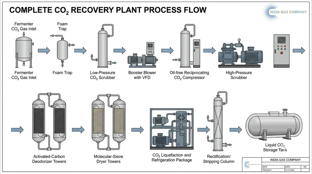
Every CO2 Recovery Plant Setup follows a broadly similar process sequence, though equipment sizing and configuration vary with capacity. The typical flow includes:
- Raw CO2 gas intake from the fermenter, through a foam trap
- Low Pressure (LP) CO2 gas scrubbing to remove water-soluble impurities such as ethanol and acetaldehyde
- Booster blower with VFD to raise gas pressure for downstream processing
- CO2 gas compression in a non-lubricated, oil-free reciprocating compressor
- High Pressure (HP) CO2 gas scrubbing for a second stage of impurity removal
- Dual tower deodorizing using activated carbon to remove non-water-soluble, odor-causing impurities
- Dual tower drying to reduce moisture to a dew point of around -60°C
- Liquefaction of the purified CO2 vapor through a refrigeration system
- Rectification/stripping to remove residual non-condensable gases and achieve final purity
- Storage of the finished liquid CO2 in insulated bulk storage tanks
This sequence is the backbone of nearly every modern CO2 Recovery Plant Setup, whether designed for a small brewery or a large-capacity distillery.
Key Equipment in a CO2 Recovery Plant Setup
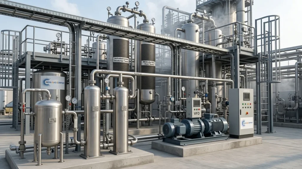
1. Booster Blower with VFD
The booster blower raises the pressure of raw CO2 gas coming from the fermenter so it can move through the rest of the CO2 Recovery Plant Setup. A Variable Frequency Drive (VFD) allows the blower to adjust to fluctuating gas generation rates, improving energy efficiency.
2. CO2 Foam Trap
Installed between the fermenter and the recovery system, the foam trap prevents foam carryover from contaminating downstream equipment a small but important safeguard in any CO2 Recovery Plant Setup.
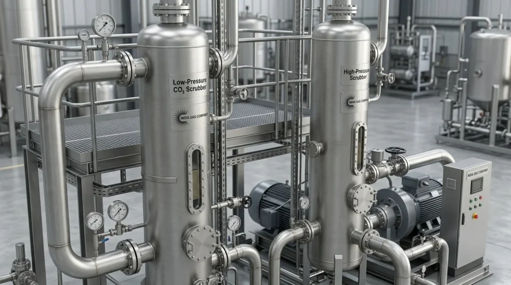
3. Low Pressure and High Pressure CO2 Gas Scrubbers
Constructed in stainless steel with structured packing, these scrubbers remove water-soluble impurities such as ethanol and acetaldehyde with removal efficiencies exceeding 99.9%. Once-through scrubbing(without recirculation pumps) reduces operating costs an important efficiency factor in any well-designedCO2 Recovery Plant Setup.
4. CO2 Gas Compressor
A non-lubricated, oil-free, two-stage reciprocating compressor is generally specified, since even trace petroleum lubricant cannot be tolerated in food-grade CO2. Stainless steel valves, Teflon piston rings, and Teflon piston rod packing extend equipment life.
5. Dual Tower Deodorizer and Dryer
The deodorizer uses activated carbon in a dual-tower configuration, allowing one tower to regenerate via steam while the other remains on-stream. The dryer, typically carbon steel construction with molecular sieve media, brings the gas down to an outlet dew point of approximately -60°C at atmospheric pressure.
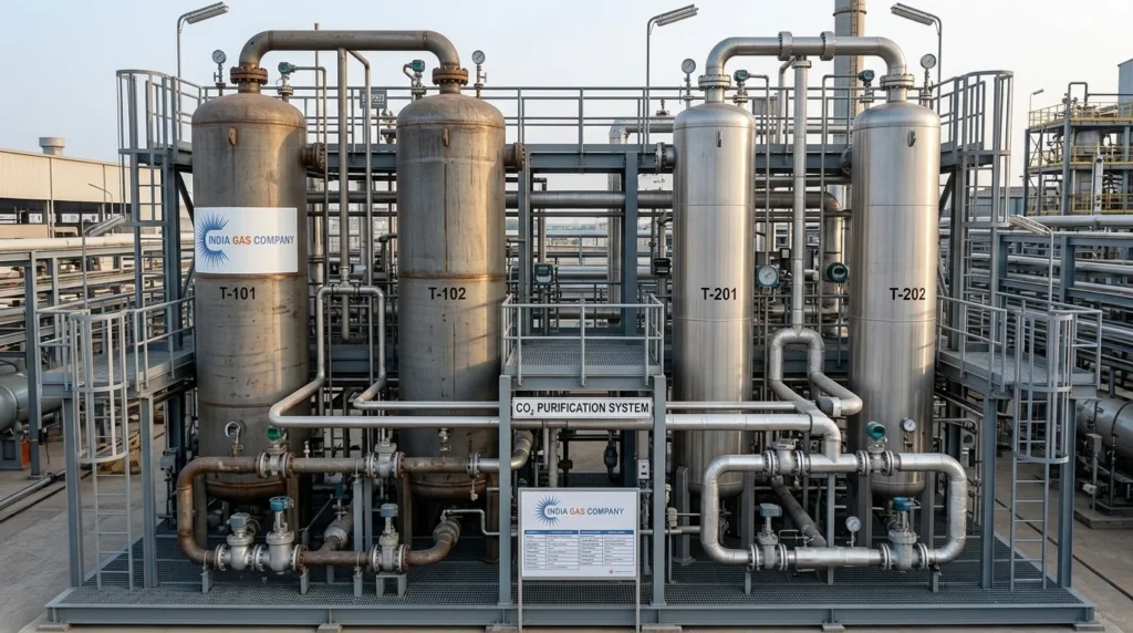
6. CO2 Liquefaction System
The liquefaction package cools CO2 vapor to around -26°C at approximately 17.5 bar(a), converting it to liquid form. This section usually includes a refrigerant condenser/receiver, CO2 condenser, precooler, and anammonia-based refrigeration system with reciprocating compressors.
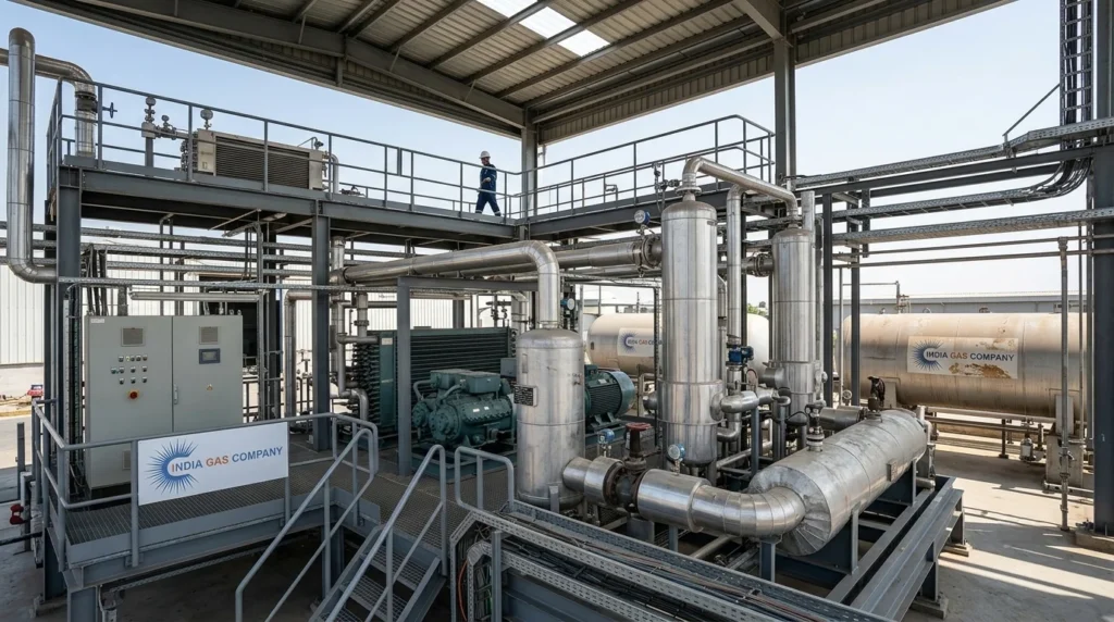
7. CO2 Rectifier/Stripper with Reboiler
Mounted between the CO2 condenser and the storage tank, the rectifier/stripper improves final product quality by lowering oxygen content, stripping the liquid CO2 with pure vapor CO2 in a packed column.
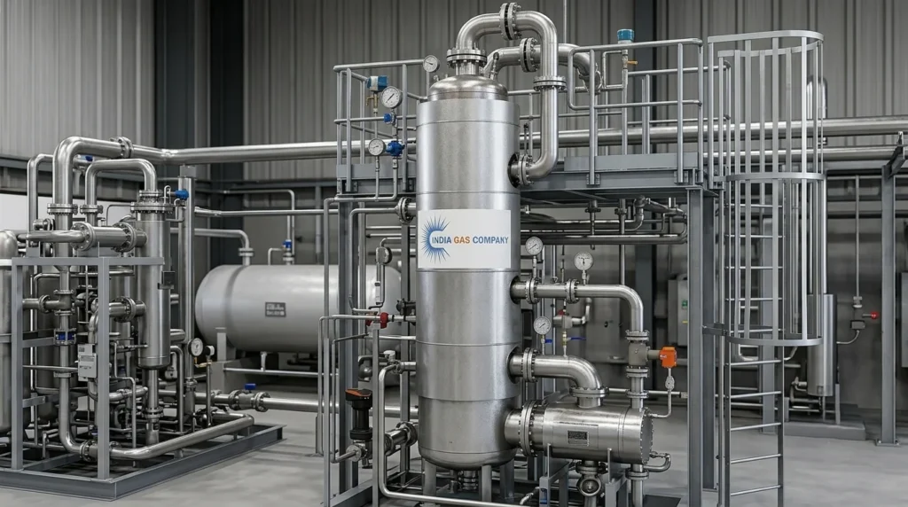
8. Bulk CO2 Storage Tanks
Storage tanks, typically horizontal, insulated with 200 mm thick polyurethane and clad in aluminum hold the finished liquid CO2. Tanks are equipped with load cells for weight measurement, external refrigeration systems, safety valves, process valves, and level gauges.
9. PLC Control Panel with MCC
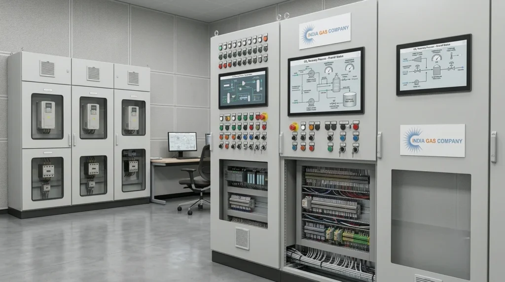
A centralized PLC-based control system with Motor Control Center (MCC) automates and monitors the entire CO2 Recovery Plant Setup, with HMI-based visualization and status indication (Run/Stop/Trip).
Technical Specifications of a Typical CO2 Recovery Plant Setup
To illustrate what a real-world CO2 Recovery Plant Setup looks like on paper, here are representative design parameters for a grain-based ethanol distillery application with a capacity of 1,700 kg/hr (equivalent to roughly 40 MTPD):
| Parameter | Specification |
| Capacity | 1,700 kg/hr liquid CO2 |
| CO2 Purity (Product) | 99.99% v/v (Food Grade) |
| Oxygen Content | < 10 ppm max |
| Raw CO2 Gas Purity (Input) | 95–97% v/v (min.) |
| Raw Gas Temperature | 35–40°C |
| Raw Gas Pressure | 200–300 mm WC |
| Power Supply | 440–480 V, 3 phase, 60 Hz, 4-wire; ~395 kWh |
| Control Voltage | 220–240 V, 1 phase, 60 Hz |
| Steam Supply | 150°C, 3.0–3.5 kg/cm²g, 200 kg/hr (twice weekly, 12 hrs, for regeneration) |
| Cooling Water | 32°C, 2.5–3.0 kg/cm²g, 276 m³/hr |
| Process Water | 1.05 m³/hr (LP and HP scrubbers) |
| Dryer Outlet Dew Point | -60°C at atmospheric pressure |
| Liquefaction Pressure | 17.5 bar (a) |
| Liquefaction Temperature | -26°C |
These figures highlight an important principle behind any efficient CO2 Recovery Plant Setup: the system must be designed to accept relatively low-purity raw gas (as low as 95% v/v, with the ability to handle input down to even lower levels) and still consistently deliver 99.99% v/v food-grade output. This margin of tolerance is what makes a CO2 Recovery Plant Setup robust against day-to-day fluctuations in fermentation gas quality.
Storage Tank Design in a CO2 Recovery Plant Setup
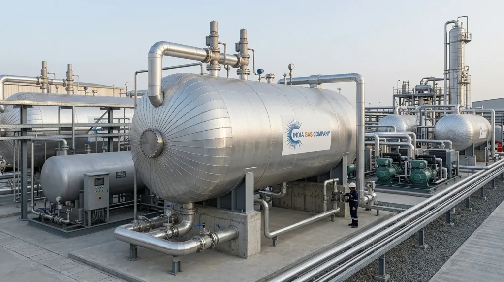
Bulk storage is a critical, often underestimated, component of any CO2 Recovery Plant Setup. Typical design norms for horizontal CO2 storage tanks include:
- Design pressure: 24 bar + static pressure
- Design temperature: -45°C to -18°C (shell), -45°C to +55°C (coil)
- Operating pressure: 19.5 bar
- Operating temperature: below -26°C
- Filling ratio: 0.9
- Hydro test pressure: 35 kg/cm²g
- Radiography: 100%
- Insulation: 200 mm thick, 20 SWG aluminum cladding
- Materials: SA 516 Gr. 70 (shell/dish end), SA 333 Gr. 6 (nozzle pipes), SA 350 LF2 (nozzle flanges)
Fabrication for tanks in a CO2 Recovery Plant Setup generally follows IS 2825 Cl-1, 1969 with AMD-1, 1977,along with SMPV(U) 1981 codes, and flanges conforming to ANSI B16.5. Stage-wise inspection by a Third Party Inspection Agency (TPIA), 100% radiography and liquid penetrant testing of butt welds, and stress relieving are standard quality checkpoints.
Reference Capacities Seen Across CO2 Recovery Plant Setup Projects
CO2 Recovery Plant Setup installations vary widely in scale depending on the size of the parent distillery or brewery. The chart above shows representative plant capacities (in MTPD) drawn from a set of real distillery and chemical-industry reference projects ranging from smaller 12–15 MTPD installations suited to modest breweries, through the common 25–30 MTPD range for mid-sized distilleries, up to large 60–150 MTPD systems for high-throughput operations.
This spread illustrates that a CO2 Recovery Plant Setup is not a one-size-fits-all system; it is engineered around the specific gas generation rate of the source fermentation process.
Utility and Infrastructure Considerations
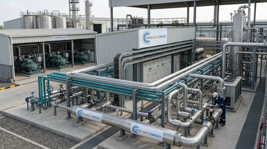
Before finalizing a CO2 Recovery Plant Setup, plant owners need to plan for the following utilities, since consistent supply directly affects recovery efficiency:
Power: A stable electrical supply is essential, since compressors, blowers, and refrigeration units are the most power-intensive components of the CO2 Recovery Plant Setup.
Steam: Used primarily for periodic regeneration of the deodorizer and dryer beds; typically required only a few times a week rather than continuously.
Cooling Water: Needed for the refrigerant condenser and CO2 condenser; supply temperature and flow rate directly affect liquefaction efficiency.
Process Water: Used in the LP and HP scrubbers for impurity removal, generally required in modest volumes compared to cooling water.
An efficient CO2 Recovery Plant Setup is engineered to minimize utility consumption per ton of CO2 produced, since power, steam, and water costs are the primary ongoing operating expenses once the plant is commissioned.
Quality Assurance in a CO2 Recovery Plant Setup
Because the end product is often food-grade and destined for beverage carbonation, quality assurance is non-negotiable in any serious CO2 Recovery Plant Setup. Key quality practices include:
- Reflux condensers at the stripper column to prevent CO2 vapor loss
- High-efficiency demister pads to eliminate entrained water droplets before the gas reaches the compressor
- CIP (Clean-In-Place) systems for scrubbers, reducing manual cleaning downtime
- Manual and automated dew point testers for periodic verification of dryer performance
- CO2 purity testers to confirm product specification before dispatch
Choosing Equipment Materials for a CO2 Recovery Plant Setup
Material selection has a direct bearing on the longevity and reliability of a CO2 Recovery Plant Setup. Since wet CO2 gas is mildly corrosive (particularly before the drying stage), stainless steel construction is standard for scrubbers, foam traps, and piping up to the dryer inlet.
Downstream of the dryer, where the gas is dry,seamless carbon steel piping is typically used for the balance of the CO2 Recovery Plant Setup, helping to control costs without compromising on system integrity.
Erection, Commissioning, and Ongoing Operation
A CO2 Recovery Plant Setup does not end with equipment supply proper site erection and commissioning are equally important.
This typically includes interconnecting piping, electrical wiring and conduit between components and the MCC, initial charging of activated carbon, molecular sieve, and refrigerant, followed by trial runs to confirm that the plant consistently meets its design purity and capacity.
Ongoing operation of a CO2 Recovery Plant Setup also requires periodic maintenance of compressor valves, scrubber packing, and dryer/deodorizer media to sustain performance over the plant’s operating life.
Conclusion
A well-designed CO2 Recovery Plant Setup transforms what would otherwise be a wasted fermentation by-product into a valuable, food-grade commercial product.
From the initial gas scrubbing stages through compression, deodorizing, drying, liquefaction, and final bulk storage, each stage of a CO2 Recovery Plant Setup plays a specific role in ensuring the finished CO2 meets 99.99% v/v purity, the benchmark accepted by leading global beverage companies.
Whether you are planning a CO2 Recovery Plant Setup for a grain-based ethanol distillery, a brewery, or a chemical process facility, understanding these technical fundamentals like capacity, purity targets, utility requirements, and storage tank design is the first step toward a reliable, efficient, and long-lasting installation.
You May Like:
🔗 Buy Liquid CO2 in Bangalore – High-Purity Liquid Carbon Dioxide Supplier
🔗 CO₂ Recovery Plant Setup and CO₂ Production Plant Setup: Complete Guide


1 thought on “CO2 Recovery Plant Setup: A Complete Technical Guide”